How to Choose the Best PT100 RTD Sensor?
Choosing the best pt100 RTD sensor is not simply a matter of selecting the tightest accuracy class. The right choice depends on process temperature, required uncertainty, response time, installation geometry, and exposure to vibration or corrosive media. A probe measuring a stable tank may perform well with a different construction than one installed in a fast-moving pipe. Small details matter: sheath material, insertion depth, and whether the connection uses two, three, or four wires.
IEC 60751:2022 defines key requirements for industrial platinum resistance thermometers. For a Class A sensor, its tolerance at 0°C is ±0.15°C; the permitted error increases with temperature. That figure describes the sensor tolerance, not the accuracy of the entire installed measurement chain. NIST Technical Note 1297 also stresses evaluating measurement uncertainty, a useful reminder when choosing a sensor, transmitter, and calibration plan together. A catalog can still mislead.
William Thomson, Lord Kelvin, wrote, “When you can measure what you are speaking about, and express it in numbers, you know something about it.” For pt100 RTD selection, that means checking the actual operating range and installation conditions, not relying on a headline specification. A careful comparison should include tolerance, stability, response time, wiring, and calibration traceability. It should also acknowledge what remains uncertain: real-world drift and mounting effects can be difficult to predict from a datasheet alone.
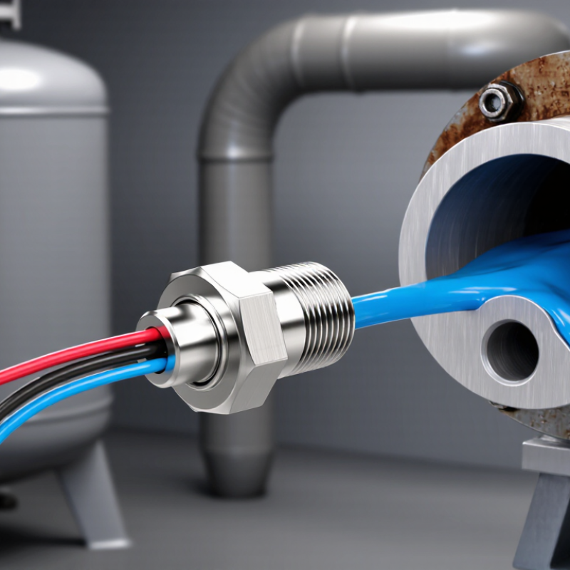
Understand How PT100 RTD Sensors Measure Temperature
A PT100 measures temperature through the changing electrical resistance of a platinum element. “PT” refers to platinum, and “100” means the element has a nominal resistance of 100 ohms at 0°C. As temperature rises, its resistance rises in a predictable way. A measurement instrument reads that resistance and converts it into a temperature value.
The change is small, so the measurement circuit matters. A two-wire connection can include resistance from the cable, creating an error—especially with long leads. Three-wire wiring compensates for much of this effect, while four-wire measurement can reduce it further.
Small detail. The sensor also needs a small measuring current; too much current can warm the element and distort the reading. This is called self-heating.
In practice, the reading depends on more than the sensing element. Installation, wiring, calibration, and the surrounding temperature all affect accuracy. For example, a probe pressed against a cold pipe may respond differently from one exposed to moving air. Allow time for it to settle. A PT100 is useful, but it is not magically exact; checking the full measurement setup is easy to overlook.
Define Your Temperature Range and Accuracy Requirements
Before choosing a PT100, write down the lowest and highest temperatures it will actually measure. IEC 60751 specifies a broad sensor range, but the probe sheath, insulation, cable, and process connection can narrow it. A cold room may need stable readings near −40°C; a heated pipe may face repeated swings above 200°C. Check the full assembly’s rated range, not just the sensing element. Small detail, big difference.
Set the required accuracy at the measurement point. IEC 60751 gives Class A tolerance as ±(0.15 + 0.002|t|)°C and Class B as ±(0.30 + 0.005|t|)°C, where t is temperature in Celsius. At 100°C, that means ±0.35°C for Class A and ±0.80°C for Class B. These are sensor tolerances, not guaranteed system accuracy. Lead-wire resistance, calibration drift, installation depth, and transmitter error can all add uncertainty. In practice, a precise element mounted in a poor thermal location can still give a misleading reading.
Tips: Compare tolerance at your actual operating temperature, then add the errors from wiring and readout equipment. For long cable runs, consider a three- or four-wire connection. It costs more. Sometimes that is unnecessary—but overlooking the cable can undermine the accuracy you paid for. Refer to IEC 60751 for tolerance definitions and verify the selected probe’s datasheet before ordering.
Choose the Probe Design and Installation Method
Choose a PT100 probe that matches the temperature range, space, and response time your process requires. A thin sheath responds quickly, but may be less durable in abrasive or high-vibration conditions. A thicker probe tolerates tougher service, though it can react more slowly to sudden temperature changes. For tanks and pipes, check the insertion length and diameter against the available opening. Too little immersion can let the fitting conduct heat away from the sensing element. A surface probe suits accessible flat equipment, but contact pressure and insulation affect its readings. Small details matter.
Installation is just as important as probe design. Place the sensing tip where the material is well mixed, not beside a wall, heater, or stagnant pocket. In a pipe, insert the probe far enough into the flow to reduce errors from the pipe surface. A thermowell can protect the sensor and allow replacement without draining equipment, but it adds thermal lag. Route the cable away from motor power wiring, and secure it against vibration. I would not assume the first location is ideal; compare readings at nearby points when practical.
Tips: Confirm the probe’s wiring configuration before connecting it. Use a suitable sealed fitting in wet areas, and leave room for removal. Check readings against a trusted reference during commissioning.
Match the Wiring Configuration to Your Measuring Equipment
How to Choose the Best PT100 RTD Sensor?
Match the Wiring Configuration to Your Measuring Equipment
Before choosing a PT100 sensor, check the input terminals and configuration supported by your measuring equipment. A sensor and instrument can both be suitable, yet give inaccurate readings when their wiring methods do not match. Check the equipment manual, not just the terminal labels. That matters.
A two-wire connection is simple and often practical for short cable runs. However, the instrument also measures resistance from the lead wires, which can shift the temperature reading. A three-wire connection compensates for lead resistance when the wires are similar in length and resistance. This is common in industrial measurement, but it is not perfect if cable conditions differ. A four-wire connection uses separate pairs for current and voltage measurement, reducing the effect of lead resistance. Choose it when your instrument supports it and accuracy requirements justify the extra wiring.
A practical check is to confirm the sensor’s wire count, terminal layout, and input setting before installation. Look for loose connections, long cable runs, and routes near motors or power cables, which may introduce noise. Keep it simple. Do not assume that matching wire colors alone confirms a correct connection; color conventions can vary. If readings drift, compare the instrument’s configuration with the sensor wiring and check the lead connections before replacing the sensor.
Evaluate Materials, Durability, Calibration, and Certifications
How to Choose the Best PT100 RTD Sensor?
Start with the process conditions, not just the temperature range. A PT100 has a nominal resistance of 100 ohms at 0°C, with a standard coefficient of 0.00385 ohms per ohm per degree Celsius under IEC 60751. For wet, corrosive, or vibrating installations, match the sheath material and probe construction to the actual environment. A polished metal sheath may resist corrosion, but it cannot compensate for a poor seal or repeated mechanical stress. Small details matter.
Accuracy should be checked against IEC 60751 tolerance classes. At 0°C, its Class A tolerance is ±0.15°C, while Class B is ±0.30°C. These limits do not guarantee the same performance after years of thermal cycling. Request calibration results at temperatures close to your operating points, and look for traceability and uncertainty details. ISO/IEC 17025 accreditation can support confidence in the calibration laboratory, but it does not replace checking whether the stated uncertainty suits your application.
Tips: Confirm insertion depth, connection type, and calibration interval before ordering. Keep the calibration certificate with maintenance records. A useful reflection: the most precise sensor on paper may be the wrong choice if it is difficult to install or protect.
How to Choose a PT100 RTD Sensor: Compare Tolerance Classes
Maximum permissible temperature deviation at selected temperatures, according to IEC 60751
Lower deviation means tighter temperature tolerance. Values are calculated using the IEC 60751 formulas: Class AA ±(0.1 + 0.0017 × |t|) °C, Class A ±(0.15 + 0.002 × |t|) °C, Class B ±(0.3 + 0.005 × |t|) °C, and Class C ±(0.6 + 0.01 × |t|) °C. When selecting a sensor, also check sheath and element materials for process compatibility, construction for durability, calibration documentation, and required certifications. Tolerance class alone does not guarantee overall sensor performance.